Creating a rotating magnetic field
There are no JavaScript simulations on this page. The figures presented are animated .gifs created from a script in python, and an background image. The original version of this script is from Josh Lifton (2004). Curves and arrows are plotted using the Matplotlib library.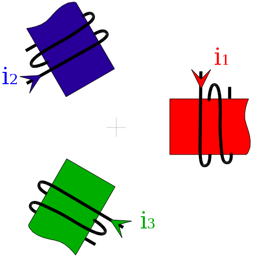
A rotating magnetic field can be created using three windings, spaced 120° degrees apart, and powered by balanced three-phase currents. FIG. 1 schematically represents these three windings. In figure 1a, only the first phase (red) is energized. In figure 1b, only the second phase (blue) is energized. Finally, in figure 1c, phase 3 (green) is energized.
 (a)
(a) (b)
(b) (c)
(c)In figure 2, the three coils are supplied by three-phase currents, with a phase difference of 120° between each. The vectors representing the magnetic fields are plotted separately in Figure 2a. They are placed end-to-end in Figure 2b. Finally, in Figure 2c, the sum of the three vectors is shown in black. This sum corresponds to the extremity of the three vectors placed end-to-end. The black arrow therefore represents the resulting magnetic field obtained by energizing the three coils. This resulting field can:
- spin a permanent magnet (principle of synchronous motors);
- induce an electromotive force in a coil;
- spin a short-circuited winding (principle of induction motors).
 (a)
(a) (b)
(b) (c)
(c)